


T: +86-19511798062
E: sales@honestflex.com
E: sales@honestflex.com
Licang District, Qingdao, Shandong, China
Views: 0 Author: Site Editor Publish Time: 2026-08-18 Origin: Site


Specifying the wrong camlock fitting size introduces severe operational hazards. Catastrophic leaks, sudden pressure drops, and unplanned system downtime quickly follow incorrect sizing. Safety risks escalate exponentially in high-pressure fluid transfer applications where hazardous chemicals or scalding liquids are present. A blown connection puts personnel at immediate risk and damages expensive surrounding infrastructure.
Sizing is rarely as simple as matching a single nominal dimension. Buyers must perfectly align the hose inside diameter (ID), pipe thread standards, and the specific outside and inside diameters (OD/ID) of the mating cam and groove components. A two-inch hose does not automatically guarantee a standard two-inch fitting will mate securely without verifying the underlying connection standards.
We use precise measurement techniques and industry-standard selection frameworks to evaluate and select the correct fittings. By referencing a comprehensive camlock coupling size chart, operators eliminate guesswork, ensure leak-free operations, and maintain strict safety compliance across all fluid transfer systems.
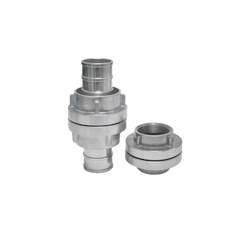
Nominal Size vs. Actual Dimensions: The nominal size of a camlock refers to the pipe or hose it connects to, not the physical measurement of the coupling's mating parts.
Measurement Precision: Accurate selection requires measuring the Outside Diameter (OD) of the male adapter and the Inside Diameter (ID) of the female coupler using digital calipers, avoiding the inaccuracies of standard tape measures.
Pressure Limitations: Maximum working pressure inversely correlates with coupling size; larger camlocks (e.g., 6" or 8") handle significantly lower pressures than standard 1" or 2" sizes.
Thread Compatibility: Matching the physical size is insufficient if the thread standards (NPT vs. BSP) or connection types do not align with the existing piping infrastructure.
Table of Contents
Engineers and procurement teams need a reliable reference point to verify component compatibility. You must ensure that male and female components from different batches or manufacturers will successfully mate. Relying on visual estimation leads to immediate field failures and dangerous blowouts. The data below provides exact dimensions to ensure Mil-Spec compliance and a secure mechanical lock.
Standard Dimensions for Cam and Groove Fittings
Nominal Size (Inches / mm) | Male Adapter Outside Diameter (OD) | Female Coupler Inside Diameter (ID) | Standard Hose ID Compatibility |
|---|---|---|---|
1/2" (15mm) | 0.95" (24.1mm) | 0.98" (24.9mm) | 1/2" |
3/4" (20mm) | 1.26" (32.0mm) | 1.29" (32.8mm) | 3/4" |
1" (25mm) | 1.44" (36.6mm) | 1.47" (37.3mm) | 1" |
1-1/4" (32mm) | 1.78" (45.2mm) | 1.81" (46.0mm) | 1-1/4" |
1-1/2" (40mm) | 2.10" (53.3mm) | 2.14" (54.4mm) | 1-1/2" |
2" (50mm) | 2.48" (63.0mm) | 2.52" (64.0mm) | 2" |
2-1/2" (65mm) | 2.98" (75.7mm) | 3.02" (76.7mm) | 2-1/2" |
3" (80mm) | 3.60" (91.4mm) | 3.64" (92.5mm) | 3" |
4" (100mm) | 4.70" (119.4mm) | 4.74" (120.4mm) | 4" |
5" (125mm) | 5.73" (145.5mm) | 5.77" (146.6mm) | 5" |
6" (150mm) | 6.92" (175.8mm) | 6.96" (176.8mm) | 6" |
8" (200mm) | 8.91" (226.3mm) | 8.95" (227.3mm) | 8" |
Standard sizes ranging from 1/2-inch through 4-inch remain readily available across global supply chains. Facilities use these heavily in chemical processing, petroleum transport, and dry bulk handling. You will find 2-inch and 3-inch fittings on almost every vacuum truck and fuel delivery tanker on the road. They offer a reliable balance of flow rate and manual handling weight for operators connecting hoses by hand.
Sizes like 6-inch and 8-inch serve specialized high-volume, low-pressure applications. You will typically see these massive fittings in agricultural irrigation, municipal wastewater bypasses, or bulk water transfer operations. A single 8-inch aluminum fitting weighs significantly more than a standard 2-inch component, requiring mechanical assistance or multiple operators to couple safely.
These larger components often require custom sourcing. Because tolerances compound at larger diameters, strict verification against a camlock coupling size chart becomes mandatory to ensure cross-brand compatibility. A fraction of an inch of variance on an 8-inch fitting prevents the cam arms from locking down, rendering the entire hose assembly useless on the job site.
Accurate measurement prevents catastrophic decoupling under pressure. Never assume a fitting's size based solely on the hose it attaches to. You must verify the physical dimensions of the mating surfaces before putting any system under load.
Before deploying measuring tools, inspect the fitting body for cast or stamped manufacturer markings. Quality fittings feature raised lettering indicating the nominal size and material grade. For example, a stamp reading "200 SS" indicates a 2-inch stainless steel fitting. These markings serve as a baseline for verification. Heavy field use, abrasive media, or aggressive cleaning chemicals often wear these stamps away. When markings are illegible, manual measurement is the only safe path forward.
Standard tape measures and plastic rulers lack the precision required for fluid power applications. A millimeter of variance determines whether a seal holds or fails. Mandate the use of Vernier or digital calipers for all OD/ID verification. Calipers provide exact decimal readings, preventing micro-leaks and ensuring strict compliance with Mil-Spec A-A-59326 standards. Calibrate your tools regularly to maintain accuracy in harsh industrial environments.
The male adapter features a grooved plug head that inserts into the female coupler. Accurate OD measurement dictates the security of the final connection. Follow these steps to verify the adapter size:
Wipe the plug head clean of debris, dried media, or grease using a solvent rag. Any buildup throws off the caliper reading.
Open the digital caliper jaws and place them squarely across the widest part of the male plug head, just above the locking groove.
Record the Outside Diameter (OD) reading and compare it to the standard dimensions table.
Measure the depth and width of the locking groove. Excessive wear in the groove prevents the female cam arms from seating properly, resulting in excessive play and potential decoupling.
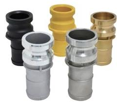
The female coupler houses the cam arms and the internal sealing gasket. Measuring the ID requires careful caliper placement to avoid false readings. Follow these steps to verify the coupler size:
Fully open both cam arms to ensure they do not obstruct the opening.
Insert the internal measurement jaws of the caliper into the open end of the coupler.
Expand the jaws until they make firm contact with the inner walls, keeping the tool perfectly perpendicular to the fitting body.
Inspect the internal gasket seating area. A crushed, swollen, or missing gasket alters the effective depth and compromises the seal, even if the ID measures correctly.
Matching the cam and groove ends solves only half the equation. The opposite end of the fitting must integrate seamlessly with your existing piping infrastructure. Thread identification requires specific tools and visual inspection.
NPT vs. BSP Thread Identification
Feature | National Pipe Thread (NPT) | British Standard Pipe (BSP) |
|---|---|---|
Thread Angle | 60 degrees | 55 degrees |
Peak and Valley Shape | Flattened peaks and valleys | Rounded peaks and valleys |
Primary Region | North America | Europe, Asia, Australia |
Sealing Method | Thread deformation (requires tape/dope) | Bonded seal or O-ring (BSPP) / Thread (BSPT) |
Use a thread pitch gauge to determine the exact number of threads per inch (TPI). Measure the thread OD for male threads or the thread ID for female threads using your calipers. Differentiate strictly between NPT and BSP. Never attempt to mate NPT and BSP threads. Cross-threading these standards destroys the threads and guarantees immediate failure under pressure.
Selecting the right fitting requires evaluating multiple operational variables simultaneously. The industry-standard STAMPED acronym functions as a rigorous decision-stage checklist. This framework moves buyers beyond basic physical dimensions to ensure long-term system integrity.
Size dictates flow rate and system efficiency. Reiterate the use of the camlock coupling size chart to match flow requirements and pipe diameters. Undersized fittings create severe system bottlenecks, increasing pump wear and reducing overall throughput. Oversized fittings add unnecessary weight and stress to the hose assembly. A 4-inch hose fitted with 3-inch reducers will only flow at the capacity of the 3-inch restriction.
Thermal expansion alters the effective sizing and seal integrity of different materials. Aluminum expands differently than Polypropylene under extreme heat. High temperatures soften plastic fittings, reducing their pressure retention capabilities. Polypropylene softens significantly above 150°F. A fitting that holds 100 PSI at room temperature might blow off the hose at 60 PSI when pumping hot wastewater. Conversely, freezing temperatures make certain polymers brittle and prone to shattering upon impact. You must match the fitting material and the internal gasket compound (e.g., Viton, EPDM, PTFE) to the maximum and minimum operating temperatures of your system.
The chemical composition of the transferred fluid dictates material selection. Material choice subsequently dictates available size ranges and wall thicknesses. Corrosive acids demand 316 Stainless Steel or specialized Polypropylene. Marine environments require Brass or Bronze to resist saltwater corrosion. Abrasive dry bulk materials wear down aluminum quickly, necessitating hardened steel components. Always consult a chemical compatibility chart before finalizing your selection. Pumping sulfuric acid through an aluminum fitting results in rapid degradation, leaks, and severe safety hazards.
A direct, inverse relationship exists between coupling size and maximum working pressure. Larger surface areas distribute internal forces differently. Never exceed the rated working pressure for your specific size and material combination. Account for pressure spikes and hydraulic shock (water hammer) during system startup and shutdown.
Maximum Working Pressure (PSI) by Material and Size
Nominal Size | Stainless Steel / Brass | Aluminum | Polypropylene |
|---|---|---|---|
1/2" to 2" | 250 PSI | 250 PSI | 100 PSI |
2-1/2" | 225 PSI | 150 PSI | 75 PSI |
3" | 200 PSI | 125 PSI | 50 PSI |
4" | 100 PSI | 100 PSI | 50 PSI |
6" | 75 PSI | 75 PSI | N/A |
Evaluate the required connection ends based on your infrastructure. Options include threaded ends (NPT/BSP), hose shanks (barbed), and flanged connections for permanent pipe installations. Consider delivery and volume requirements. Specialized sizes or exotic materials require longer lead times. Plan procurement cycles accordingly to avoid facility downtime while waiting for replacement parts.
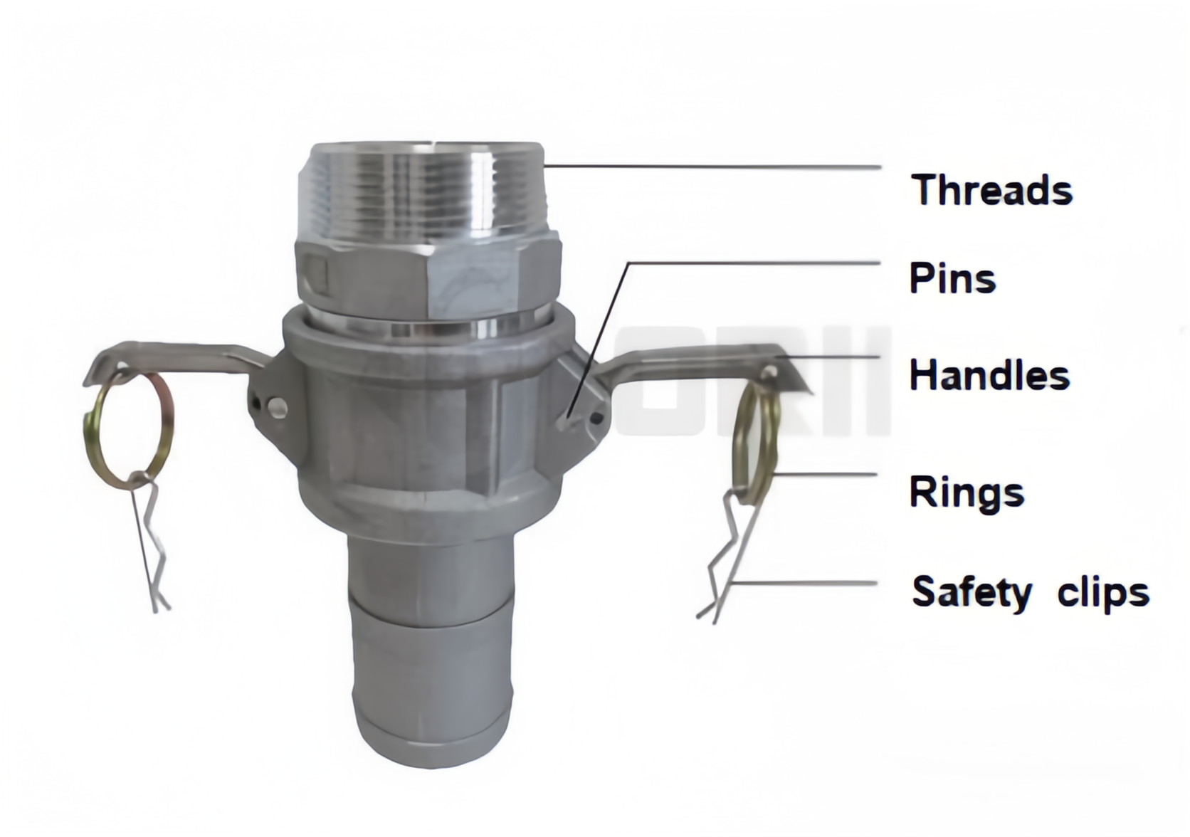
Manufacturers use a standard alphanumeric classification system to identify fitting configurations. Understanding these codes helps buyers match the right size to the correct connection type quickly and accurately.
Type C (Female Coupler to Hose Shank) and Type E (Male Adapter to Hose Shank) integrate directly into flexible hoses. Sizing considerations here are strict. You must match the hose barb OD exactly to the Hose ID. Forcing an oversized shank into a rigid hose causes micro-tearing in the hose tube, leading to premature failure. Never heat a chemical suction hose with a torch to force an oversized Type E adapter into the tube. This destroys the internal wire helix and degrades the rubber compound. Using an undersized shank guarantees blowouts under pressure. Depending on the size and application pressure, secure these connections using heavy-duty interlocking hose clamps or machine-crimped ferrules.
Threaded fittings connect flexible hoses to rigid pipe infrastructure. Type A (Male Adapter to Female Thread), Type B (Female Coupler to Male Thread), Type D (Female Coupler to Female Thread), and Type F (Male Adapter to Male Thread) dominate facility installations.
Apply strict sizing rules for matching female and male NPT or BSPT threads. Understand the nominal pipe size rule: threaded camlocks feature an actual thread OD slightly larger than the nominal pipe size. A 2-inch NPT thread measures approximately 2.375 inches in actual OD. Failing to account for this discrepancy results in ordering undersized components. Always use high-quality thread sealant tape or liquid pipe dope on male threads to prevent galling and ensure a leak-free seal.
Type DC (Dust Cap) and Type DP (Dust Plug) seal open hose ends and pipe manifolds. Size these end-caps precisely to match the mating components. Dust caps and plugs prevent environmental contamination during transit, protect internal threads during maintenance, and allow for safe system depressurization. Never use standard dust caps as pressure-holding bulkheads unless they are specifically rated and pinned for dead-end pressure applications. A standard dust cap will blow off violently if the manifold is accidentally pressurized.
Procurement and installation phases present multiple opportunities for sizing errors. Mitigating these risks requires strict attention to detail and an understanding of specific industry anomalies.
An industry anomaly exists regarding the smallest standard sizes. The 1/2-inch and 3/4-inch camlock bodies often share the exact same mating dimensions. A 1/2-inch male plug will securely lock into a 3/4-inch female coupler. The industry standard uses the exact same casting for the mating body on both sizes. However, the threaded or barbed ends differ to match their respective pipe or hose sizes. Navigate this quirk carefully. Verify the thread or shank size independently of the cam body size to ensure you do not order a fitting that mates perfectly but fails to attach to your hose.
Metal camlocks strictly follow Mil-Spec A-A-59326 / MIL-C-27487 standards, ensuring universal interchangeability. Non-metallic fittings, such as Polypropylene or Nylon, do not always adhere to these exact external dimensions. Manufacturers often design plastic fittings with thicker walls to maintain structural integrity and pressure ratings. While the mating faces remain compatible, the thicker outer body impacts tight-clearance installations. Measure the total footprint of plastic fittings if installing them in compact manifolds or tight equipment cabinets. Two polypropylene fittings mounted side-by-side on a manifold might interfere with each other's cam arms due to the increased wall thickness.
Field technicians sometimes attempt field modifications when the correct size is unavailable. Wrapping an undersized shank in tape to create a seal creates a severe blowout hazard. The tape provides zero mechanical retention against the hose clamps. Always source the exact matching size. If a transition is necessary, use properly rated threaded reducers or step-down adapters rather than compromising the hose-to-fitting interface.
Incorrect sizing extends to the internal sealing components. Using the wrong replacement gasket thickness prevents the cam arms from locking down fully. If the gasket is too thick, the arms will not reach their locked position, leading to vibration-induced decoupling. If the gasket is too thin, the arms will lock easily, but the fitting will leak fluid under pressure. Always verify gasket dimensions and material compatibility during routine maintenance cycles. Replace gaskets that show signs of chemical swelling or mechanical crushing.
Successful fluid transfer operations rely on moving beyond basic nominal sizes. Operators must strictly adhere to exact OD/ID measurements, material tolerances, and thread standards. Guesswork in fluid power applications leads directly to equipment damage, environmental spills, and safety incidents. Utilizing precision measurement tools and referencing standardized data ensures every connection remains secure under maximum working conditions.
For industrial fluid transfer projects requiring compatible hoses and connection components, Qingdao Honest Rubber Co., Ltd., operating under the Honestflex brand, manufactures and exports hydraulic hoses, industrial hoses, PVC hoses, hose couplings, and hose protection products. With a 20,000-square-meter workshop and more than 100 sets of production and testing equipment, the company provides integrated manufacturing support for customers sourcing hose and coupling solutions for diverse industrial applications.
Apply these action steps to secure your fluid transfer systems:
Audit your current fluid transfer systems using digital calipers to verify existing OD/ID measurements on all active hoses and manifolds.
Cross-reference your findings with a standardized camlock coupling size chart to identify any mismatched or out-of-spec components.
Replace any worn gaskets or deformed cam arms immediately to prevent vibration-induced decoupling during high-pressure transfers.
Standardize your facility's thread types (NPT or BSP) to eliminate cross-threading risks during rapid hose changeouts.
A: Use digital calipers to measure the exact Outside Diameter (OD) of the male plug head and the Inside Diameter (ID) of the female coupler. Never rely on standard tape measures or measure the pipe end, as these methods lack the precision required to verify a secure, leak-free mechanical seal.
A: Metal fittings manufactured to Mil-Spec A-A-59326 / MIL-C-27487 standards are universally interchangeable across different brands. Exceptions exist for polypropylene fittings, which often feature thicker walls, and proprietary designs that may not mate correctly with standard Mil-Spec components.
A: The nominal coupling size refers to the mating cam body, not the specific hose shank outer diameter. You must verify that the hose barb OD matches your exact Hose ID. Additionally, 1/2-inch and 3/4-inch bodies often share mating dimensions but feature different shank sizes.
A: NPT features a 60-degree thread angle with flattened peaks, common in North America. BSP features a 55-degree angle with rounded peaks. These thread standards are completely incompatible; attempting to mate them causes cross-threading and immediate failure.
A: A standard 2-inch stainless steel or brass fitting typically handles up to 250 PSI. Maximum pressure depends entirely on the material grade, gasket type, and operating temperature. Polypropylene or aluminum fittings of the same size carry significantly lower pressure ratings.
A: The male adapter (plug) inserts into the female coupler, which houses the locking cam arms. Standard flow-direction practices generally place the female coupler on the hose end for maneuverability, while the male adapter remains fixed to the rigid pipe or equipment manifold.
