


T: +86-19511798062
E: sales@honestflex.com
E: sales@honestflex.com
Licang District, Qingdao, Shandong, China
Views: 0 Author: Site Editor Publish Time: 2026-08-18 Origin: Site


Fluid and dry bulk transfer systems depend entirely on the integrity of their connection points. Mismatched fittings cause immediate downtime, product loss, and severe environmental hazards. Selecting the wrong cam and groove configuration, thread type, or material leads to hazardous leaks, pressure drops, system contamination, and safety compliance violations. You cannot afford to guess when dealing with high-pressure lines or volatile chemicals. Specifying the exact camlock coupling types required for secure, leak-free industrial applications demands precision. We evaluate the precise geometries, mating rules, and material constraints that dictate safe fluid transfer. Understanding the mechanical differences between adapters and couplers eliminates procurement errors and builds resilient piping infrastructure. Proper specification ensures your transfer lines operate safely under maximum load conditions without risking catastrophic blowouts or environmental spills.
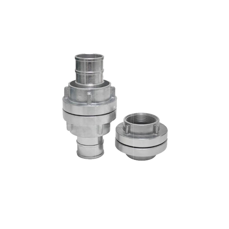
Standardized Mating: Camlock systems operate on a strict male adapter/female coupler pairing methodology. Any male adapter will fit any female coupler of the identical size, but selecting the correct termination (e.g., Type A with Type D) is non-negotiable for system design.
Termination Variables: The choice between Types A through F dictates how the fitting integrates into existing infrastructure (female/male threads vs. barbed hose shanks).
Material and Pressure Limits: Coupling type selection must be evaluated alongside material properties (Aluminum, Stainless Steel, Polypropylene) and pipeline pressure ratings, as larger diameters inherently handle lower working pressures.
System Protection: Types DC (Dust Cap) and DP (Dust Plug) are critical for protecting open lines from environmental contamination and thread damage during disconnection, but must never be used in live pressure applications.
Table of Contents
Industrial operations require rapid, tool-less connection and disconnection methods. Traditional threaded flanges take time to bolt together and require specific torque sequences, which slows down operations during frequent hose changeovers. Cam and groove systems solve this problem by providing an immediate, secure lock through a simple mechanical lever action. Understanding the baseline anatomy of these fittings prevents costly installation mistakes and ensures operators handle the equipment correctly in the field.
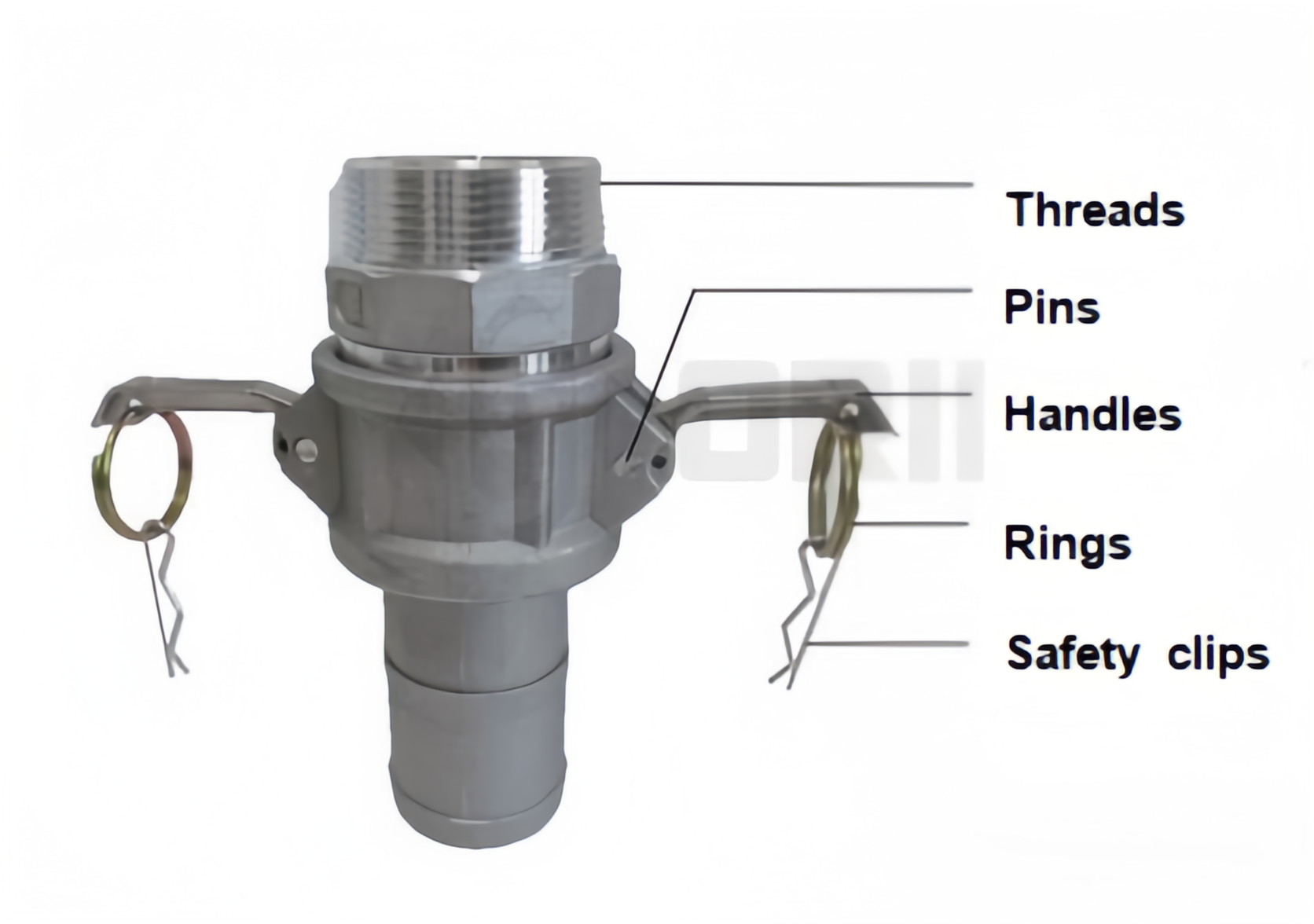
Procurement errors often stem from confusing adapters with couplers. You must identify them correctly to build a functional connection. The male component is the adapter. It functions as a grooved plug inserted directly into the mating connection. It has no moving parts, relying entirely on a precisely machined circumferential groove. The female component is the coupler. This receptacle contains the external cam arms, the pivot pins, and houses the internal elastomeric sealing gasket. When you slide the adapter into the coupler, the two halves align for locking.
The system relies on a precise mechanical action to create a hermetic seal. You fold the cam arms down against the sides of the coupler. This action forces the internal cams to engage the groove on the male adapter. The adapter pulls tightly against the internal gasket, compressing it to form a leak-proof barrier. This tool-less operation allows workers to connect large-diameter hoses in seconds while wearing heavy protective gloves.
Dimensional standardization remains mandatory for cross-brand compatibility. You can mix brands safely if they adhere to established manufacturing specifications. In the United States, the governing standard is MIL-C-27487, which was later superseded by A-A-59326. European manufacturers follow EN 14420-7 and DIN 2828. These standards dictate the exact dimensions of the cam groove, the adapter outside diameter, and the coupler inside diameter. Adherence to these standards ensures that any certified adapter will mate securely with any certified coupler of the same size.
To execute a proper connection in the field, operators must follow a strict sequence:
Inspect the internal gasket of the female coupler for tears, flattening, or chemical degradation.
Wipe the male adapter groove clean of any dirt, grit, or dried product that could prevent the cams from seating.
Insert the male adapter fully into the female coupler until it bottoms out against the gasket.
Depress both cam arms simultaneously to ensure even pressure distribution across the gasket face.
Verify the arms are fully locked flush against the coupler body.
Manufacturers categorize these fittings using a standardized lettering system from A to F, plus DC and DP. Each letter designates a specific termination geometry. You must match the termination to your existing pipe threads or hose dimensions. Below is the technical breakdown of the primary configurations used in fluid transfer.
The Type A fitting features a male adapter end designed to lock into a female coupler. The opposite end contains a female thread, typically NPT or BSP. You use this configuration to attach the adapter to rigid piping systems. Operators commonly install Type A fittings on fixed equipment outlets, manifold inputs, or tank bulkheads. It provides a permanent, rigid mounting point where hoses can be quickly attached using a mating coupler. When installing a Type A fitting onto a male pipe thread, you must apply appropriate thread sealant tape and pipe dope to prevent galling and ensure a leak-free threaded joint.
A Type B fitting consists of a female coupler equipped with cam arms. It terminates in a male thread. You thread this fitting directly into female-threaded ports on fixed equipment. Common applications include connecting flexible hoses to fixed bulkheads, distribution manifolds, or isolation valves. The male thread provides a secure anchor into the piping infrastructure, while the coupler end remains ready to receive any male adapter. Because the Type B houses the gasket and moving parts, it is often installed on the supply side of a system where it can be easily inspected and maintained.
The Type C configuration features a female coupler that transitions into a barbed hose shank. You insert the shank directly into the open end of a flexible industrial hose. This connection requires secondary securing methods. You must use heavy-duty hose clamps, interlocking ferrules, or crimped sleeves to achieve a blowout-proof attachment. Standard worm-gear clamps do not provide sufficient 360-degree clamping force for high-pressure industrial hoses. Field technicians must use banded clamps or hydraulic crimping machines to secure the hose wall into the serrations of the shank.
Type D fittings provide a female coupler that terminates in a female thread. You thread this component directly onto male pipe ends. Operators frequently pair Type D couplers with Type A adapters to create rigid-to-rigid or rigid-to-hose transitions. This configuration allows you to convert a standard male pipe thread into a quick-connect receptacle instantly. Like the Type B, the Type D fitting contains the wear components (gasket and arms), making it a primary focus during routine maintenance sweeps.
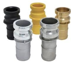
The Type E fitting consists of a male adapter transitioning into a barbed hose shank. Like the Type C, you insert the shank into a flexible hose and secure it with industrial banding or crimped sleeves. You typically install Type E adapters at the end of a hose assembly. This allows the hose to connect swiftly to fixed Type C, D, or B couplers mounted on pumps or tanks. A standard industrial hose assembly usually features a Type C on one end and a Type E on the other, allowing multiple hoses to be daisy-chained together over long distances.
Type F fittings feature a male adapter terminating in a male thread. You thread this fitting into female ports on tanks, pumps, or strainers to create an immediate quick-connect point. It serves a similar function to the Type A but accommodates female-threaded infrastructure instead of male-threaded pipes. Type F adapters are highly common on the discharge ports of trash pumps and chemical transfer pumps.
System protection requires dedicated blanking components. The Type DC (Dust Cap) slides over a male adapter and locks down with cam arms. The Type DP (Dust Plug) inserts into a female coupler and provides the groove for the arms to lock against. These components keep dirt, moisture, and pests out of open lines. They also protect precision machined threads and grooves from physical damage during transit or storage.
Dust Caps and Dust Plugs must never be used in pressure applications to seal an active line. They lack the structural integrity to withstand line pressure and will blow out, causing severe injury or chemical spills. Always use properly rated blind flanges or isolation valves to stop active flow.
Industrial applications sometimes require edge-case configurations beyond the standard A-F lineup. Type M fittings feature male adapters on both ends, acting as spool adapters to connect two female couplers. Flanged camlocks integrate a standard ANSI or DIN flange on one end, eliminating the need for threaded transitions on large-diameter pipe networks. Socket weld and butt weld camlocks allow operators to weld the fitting directly to the pipe, entirely eliminating threaded leak paths in high-vibration environments.
Designing a reliable fluid transfer network requires strict adherence to mating rules. You cannot force incompatible components together without risking catastrophic failure. Understanding how to pair different configurations ensures safe and efficient system integration across your entire facility.
The fundamental rule of cam and groove systems is straightforward. Any male adapter (A, E, F, DP) will connect to any female coupler (B, C, D, DC) of the exact same size. A 2-inch Type A adapter will fit perfectly into a 2-inch Type C coupler. You cannot mix sizes. A 2-inch adapter will never fit a 3-inch coupler. This universal compatibility allows operators to build highly modular hose networks across different facilities, provided the nominal sizes match.
You must evaluate your existing infrastructure before specifying a pairing. Look at the pipe ends, valve outputs, and hose requirements. Map out the standard pairings to create a clear decision framework. If you have a fixed male pipe thread, you need a female threaded fitting to attach to it. If you are building a hose assembly, you need barbed shanks on both ends. Match the termination to the infrastructure, then match the adapter to the coupler.
Field installations typically rely on a few proven combinations to handle standard transfer tasks. Recognizing these standard pairings speeds up the specification process.
Type A + Type D: This combination connects rigid pipe to rigid pipe, or rigid pipe to a hose assembly. It provides a secure, threaded anchor on both sides of the connection point.
Type B + Type F: Operators use this pairing for threaded transitions. It allows you to connect a female-threaded port to a male-threaded pipe using a quick-disconnect junction in the middle.
Type C + Type E: This is the standard configuration for hose-to-hose extensions. You put a Type C on one hose and a Type E on the other, allowing you to link multiple hose lengths together rapidly.
Thread mismatch presents a severe risk on Types A, B, D, and F. The United States primarily uses National Pipe Taper (NPT) threads. Europe and many other regions use British Standard Pipe (BSP) threads. NPT threads have flattened peaks and valleys with a 60-degree angle. BSP threads have rounded peaks and valleys with a 55-degree angle.
You must never force an NPT thread into a BSP port. Doing so compromises the seal, strips the machined threads, and creates a blowout hazard under pressure. Always verify the thread standard of your existing piping before ordering threaded camlock fittings. Use thread pitch gauges and calipers to confirm the pitch and angle if the existing infrastructure is undocumented. Applying excessive torque to mismatched threads will permanently damage the fixed piping infrastructure.
Coupling material impacts longevity, chemical compatibility, weight, and overall system reliability. You must match the metal or plastic to the specific media flowing through the pipeline. An incorrect material choice leads to rapid corrosion, fluid contamination, and premature mechanical failure.
Fluid Transfer Material Specifications
Material | Primary Advantages | Common Applications | Limitations |
|---|---|---|---|
Stainless Steel (304/316) | High corrosion resistance, high temperature tolerance, maximum durability. | Food-grade transfer, pharmaceuticals, harsh chemicals, offshore environments. | Heaviest weight, highest initial investment. |
Aluminum | Lightweight, highly cost-effective, easy to handle manually. | Water transfer, hydraulic oil, petroleum products, dry bulk powders. | Susceptible to galvanic corrosion and certain strong acids/alkalis. |
Brass | Non-sparking properties, excellent thermal conductivity, resists biofouling. | Marine environments, saltwater transfer, specialized aviation fuels. | Heavy, moderate cost, tarnishes over time. |
Polypropylene / Nylon | Highly resistant to industrial acids and agricultural chemicals, extremely lightweight. | Agricultural spraying, acid transfer, low-pressure water systems. | Lower pressure/temperature thresholds, susceptible to physical cracking. |
Stainless steel represents the premium choice for demanding environments. Type 316 stainless steel contains molybdenum, which drastically increases its resistance to chlorides and industrial solvents. You specify stainless steel for food-grade applications, pharmaceutical manufacturing, and harsh chemical transfer. It handles extreme temperatures and physical abuse better than any other material. While it carries the highest upfront cost, its maximum durability prevents frequent replacement cycles. Field operators rely on stainless steel when dragging hoses across abrasive concrete floors, as it resists deformation and deep scratching.
Aluminum provides an excellent balance of strength and weight. Operators prefer aluminum fittings for large-diameter hoses because they reduce worker fatigue during manual connections. A 4-inch aluminum fitting is significantly easier to maneuver than its stainless steel counterpart. It performs exceptionally well for water, hydraulic oil, and petroleum transfer. However, aluminum is susceptible to certain corrosive chemicals. You must also avoid mixing aluminum fittings with brass components in wet environments to prevent galvanic corrosion, which will rapidly eat away the aluminum threads.
Brass offers unique metallurgical properties suited for specific hazards. Its non-sparking nature makes it mandatory in environments with explosive vapors or combustible dust. If a brass fitting is dropped on a steel deck, it will not generate a spark. Brass exhibits excellent resistance to saltwater corrosion, making it a standard choice for marine environments and ship-to-shore transfers. It handles specialized fuel transfers safely. Brass is heavier than aluminum and carries a moderate cost, but its safety profile in volatile areas justifies the specification.
Plastic fittings excel in highly corrosive chemical applications where metals would rapidly degrade. Polypropylene and nylon are highly resistant to agricultural chemicals, fertilizers, and industrial acids. They are incredibly lightweight and cost-effective. However, plastic fittings have significantly lower pressure and temperature thresholds compared to metal. They require careful handling in the field to prevent cracking or thread damage from over-tightening. Operators must never use metal wrenches on plastic camlock threads, as the mechanical advantage will easily strip the polymer.
You must address the physical limitations of camlock systems to prevent catastrophic failure and ensure workplace safety. These fittings are not designed for infinite pressure. Exceeding the manufacturer's specified limits results in blown lines, worker injury, and environmental damage. System design requires strict adherence to pressure benchmarks and proactive risk mitigation.
Camlock fittings exhibit a strict inverse relationship between coupling diameter and maximum working pressure. As the coupling diameter increases, the maximum allowable pressure significantly decreases. The larger surface area of the gasket and cam arms cannot hold back the same pounds per square inch (PSI) as a smaller fitting.
For standard metal fittings (Aluminum, Brass, Stainless Steel), a 1-inch coupling typically handles up to 250 PSI. When you scale up to a 2-inch coupling, the rating remains around 250 PSI. A 3-inch coupling handles 200 PSI, a 4-inch handles 150 PSI, and a massive 6-inch coupling is usually rated for only 75 PSI. Polypropylene fittings carry much lower ratings, often maxing out at 100 PSI for small diameters and 50 PSI for larger ones. Always consult the specific manufacturer's data sheet before pressurizing the line, and ensure your system's pressure relief valves are set below the maximum rating of your largest coupling.
The entire coupling is only as reliable as its internal gasket. The metal housing provides the structure, but the elastomer gasket creates the seal. You must match the gasket material to the fluid being transferred. Using the wrong elastomer causes the gasket to swell, crack, or dissolve entirely.
Buna-N (Nitrile): The standard factory gasket. Excellent for water, petroleum products, and general-purpose oils. It operates well in moderate temperatures but degrades quickly when exposed to strong acids.
EPDM: Highly resistant to ozone, weathering, and mild chemicals. Do not use EPDM with petroleum-based fluids, as the oil will cause the rubber to swell and push the adapter out of the coupler.
Viton (FKM): Provides superior resistance to harsh chemicals, fuels, and high temperatures. Ideal for aggressive industrial solvents and high-heat applications.
PTFE (Teflon) Encapsulated: Features a resilient core wrapped in a PTFE shell. Offers near-universal chemical compatibility for the most volatile media, though it requires more clamping force to seal due to its rigidity.
High-pulsation environments pose a severe risk to standard cam and groove systems. Pump discharges, surging fluids, and heavy machinery vibrations can cause standard cam arms to slowly work themselves loose. If the arms lift, the seal breaks, and the line blows apart.
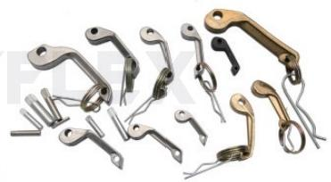
You must implement mitigation strategies in high-vibration applications. Standard cam arms feature small holes designed for safety locking pins or R-clips. Inserting these pins prevents the arms from lifting accidentally. For critical applications, specify specialized self-locking cam arms. These arms feature an integrated spring-loaded mechanism that automatically locks the lever in the closed position. The operator must manually pull a release ring to open the arm, entirely eliminating the risk of vibration-induced failure. Routine inspection must include checking the pivot pins for wear, as loose pins reduce the clamping force on the gasket.
Audit your existing hose assemblies to verify that all thread pitches (NPT/BSP) match your fixed infrastructure perfectly.
Cross-reference your fluid media against your current gasket materials using a comprehensive chemical compatibility chart.
Replace standard cam arms with self-locking variants on all pump discharge lines subject to heavy vibration.
Remove Dust Caps and Dust Plugs from any active pressure lines and replace them with properly rated blind flanges.
Building Safer and More Reliable Hose Connections
For industrial users who need camlock couplings as part of a complete hose transfer system, Qingdao Honest Rubber Co., Ltd, operating under the Honestflex brand, manufactures and exports hydraulic hoses, industrial hoses, PVC hoses, hose couplings, and hose protection products for global applications. Supported by a 20,000-square-meter workshop, more than 100 production and testing machines, and dedicated technical capabilities, the company provides integrated hose and coupling solutions for demanding fluid transfer environments.
A: Yes, you can connect them as long as they are the exact same size. Any male adapter fits any female coupler of identical diameter. However, pairing a Type A (female thread) with a Type C (hose shank) creates an uncommon rigid-to-hose transition. You typically pair a Type A with a Type D, or a Type C with a Type E.
A: NPT (National Pipe Taper) is the US standard, featuring a 60-degree thread angle with flattened peaks. BSP (British Standard Pipe) is common in Europe, featuring a 55-degree angle with rounded peaks. They are mechanically incompatible. Forcing them together causes cross-threading, severe leaks, and potential blowout hazards under pressure.
A: No. Standard camlock fittings are strictly prohibited for compressible gases, compressed air, or high-temperature steam. These media present severe explosive decompression risks. If a cam arm accidentally opens under gas or steam pressure, the sudden expansion causes catastrophic, explosive failure resulting in severe injury.
A: While mechanically possible if sizes match, mixing metals is strongly discouraged. Combining dissimilar metals like aluminum and stainless steel in a wet environment triggers galvanic corrosion, rapidly degrading the softer metal. Furthermore, the harder stainless steel will prematurely wear down the aluminum grooves. Always match materials.
A: You measure the outside diameter (OD) of the male adapter plug, not the inside of the female coupler. Use calipers to measure across the widest part of the adapter's grooved insertion end. Cross-reference this OD measurement with a standard manufacturer sizing chart to determine the nominal fitting size.
A: Dust Caps and Dust Plugs are designed solely to keep environmental contaminants out of empty, unpressurized lines. They lack the structural thickness, locking integrity, and proper gasket seating to withstand fluid pressure. Using them as dead-end pressure stops will cause them to blow off the line violently.
