


T: +86-19511798062
E: sales@honestflex.com
E: sales@honestflex.com
Licang District, Qingdao, Shandong, China
Views: 0 Author: Site Editor Publish Time: 2026-06-29 Origin: Site


Navigating the complex world of fluid power systems requires a deep understanding of the various manufacturing and performance standards that govern the components used in industrial machinery. When professionals evaluate the differences in an SAE vs DIN Hydraulic Hose, they are looking at two of the most globally recognized frameworks for ensuring safety, reliability, and compatibility in high-pressure fluid transmission. The Society of Automotive Engineers (SAE) and the Deutsches Institut für Normung (DIN) have historically provided the benchmark specifications that dictate how these critical components are constructed, tested, and deployed across diverse sectors. Understanding these standards is not just an academic exercise; it is a fundamental requirement for engineers, maintenance technicians, and procurement specialists who must select the exact right component to prevent catastrophic system failures, minimize equipment downtime, and optimize the overall efficiency of hydraulic circuits.
Understanding the specifications and construction of standard hydraulic hoses.
The distinction between these standards often comes down to regional origins and specific testing methodologies, but modern manufacturing has increasingly bridged the gap, creating components that meet or exceed the requirements of both organizations simultaneously. This dual-certification approach simplifies inventory management and ensures global compatibility for multinational operations. When a component carries both designations, users can be confident that it has been subjected to rigorous quality control measures and is capable of performing under the demanding conditions specified by both North American and European engineering authorities. This comprehensive guide will explore the intricacies of these standards, focusing on the specific materials, construction techniques, performance metrics, and application environments associated with these essential industrial components.
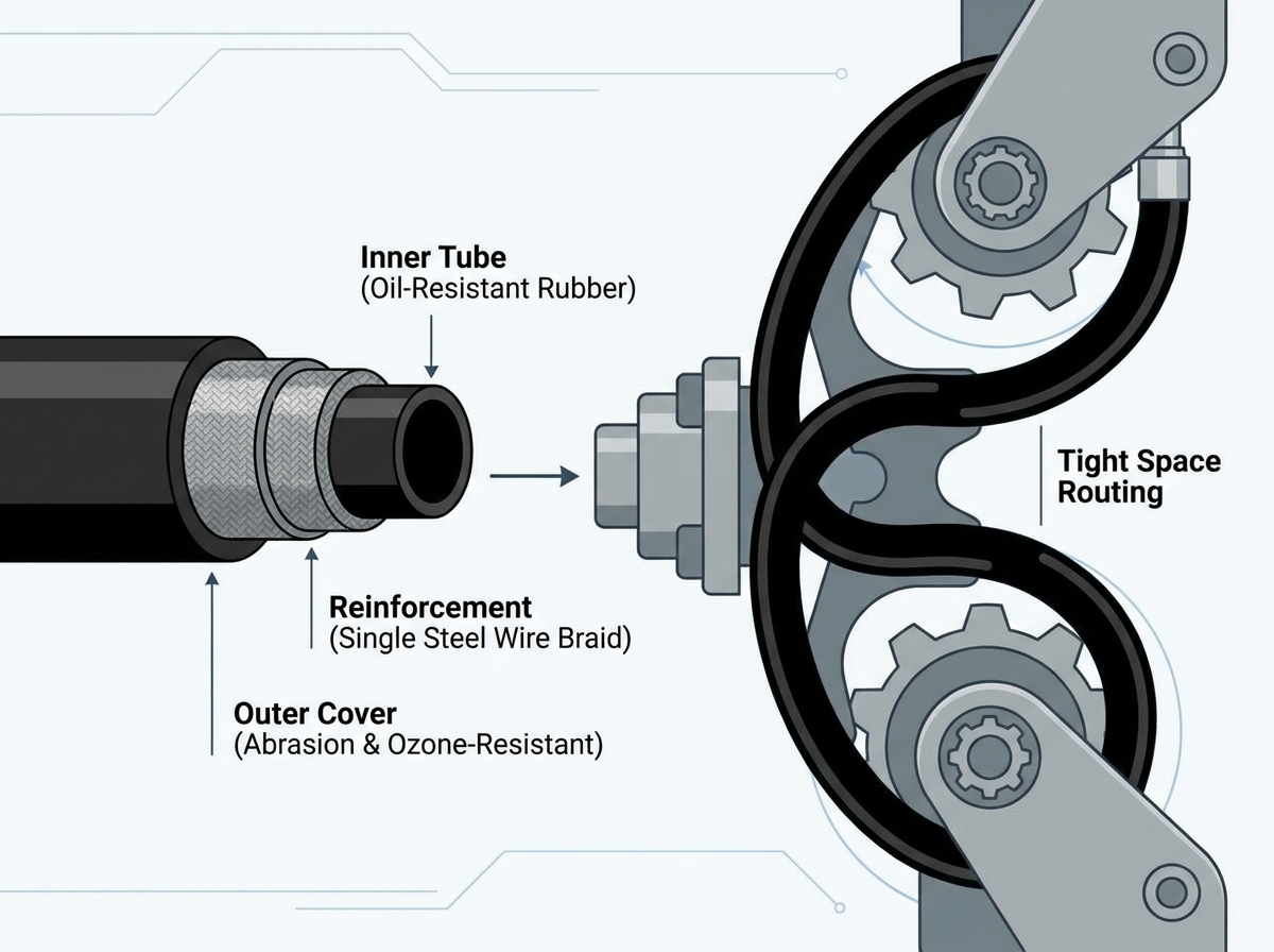
To fully grasp the implications of an SAE vs DIN Hydraulic Hose comparison, one must first look at the construction and material science that underpins these products. The core of any reliable fluid transmission line is its inner tube, which must be carefully formulated to withstand constant exposure to various chemical compounds without degrading, swelling, or losing its structural integrity. In standard medium-pressure applications, this inner tube is typically manufactured from black oil-resistant synthetic rubber, specifically NBR (Nitrile Rubber). NBR is highly regarded in the fluid power industry for its exceptional resistance to petroleum-based fluids, making it an ideal choice for the vast majority of hydraulic circuits. The integrity of this inner tube is paramount, as any failure at this level can lead to fluid contamination, pressure loss, and ultimately, system breakdown.
Surrounding the inner tube is the reinforcement layer, which provides the necessary strength to contain the high-pressure fluids coursing through the system. In medium-pressure designs, this reinforcement usually consists of one layer of high-tensile steel wire braid. This single wire braid design is a critical engineering choice that balances the need for stable pressure resistance with the requirement for physical flexibility. The high-tensile steel ensures that the component can handle significant internal forces without bursting, while the single-layer configuration allows for a tighter bending radius compared to multi-wire designs. This flexibility is a crucial attribute when routing lines through the cramped and complex compartments of modern machinery, where space is at a premium and rigid components would be impossible to install or maintain.
The outermost layer is the cover, which serves as the primary defense against the harsh external environments where these systems typically operate. Manufactured from black synthetic rubber, this outer cover provides essential resistance to abrasion, ozone, weather, and flame. Abrasion resistance is particularly important in applications where lines may rub against each other, machine chassis, or environmental obstacles during operation. Ozone and weather resistance ensure that the rubber does not become brittle or crack when exposed to sunlight and outdoor conditions over extended periods. Together, these three layers—the NBR inner tube, the high-tensile steel wire braid, and the protective synthetic rubber cover—create a cohesive unit designed to deliver reliable performance and an extended service life.
The historical development of the SAE vs DIN Hydraulic Hose standards reflects the broader evolution of industrial machinery and fluid power technology. As equipment became more powerful and compact, the demands placed on fluid transmission lines increased exponentially. Early designs struggled to balance pressure capacity with flexibility, often resulting in bulky, rigid lines that were difficult to route and prone to failure under dynamic loads. The introduction of high-tensile steel wire braiding revolutionized the industry, allowing manufacturers to produce thinner, more flexible lines that could still safely contain high pressures. The standardization provided by organizations like SAE and DIN ensured that these advancements were adopted uniformly across the industry, establishing baseline requirements for burst pressure, impulse life, and dimensional tolerances.
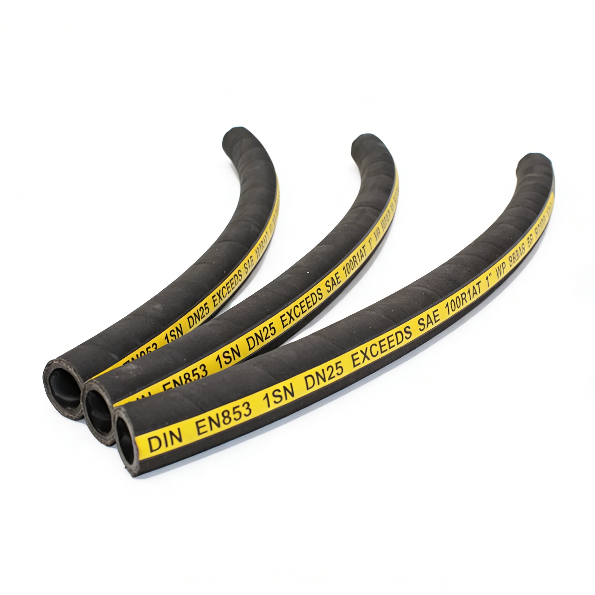
Today, the culmination of these manufacturing advancements can be seen in dual-certified products like the DIN EN853 1SN / SAE 100R1AT Hydraulic Hose manufactured by Honestflex. By meeting the stringent criteria of both the European DIN EN853 1SN standard and the North American SAE 100R1AT standard, this Honestflex product offers a versatile solution for a wide range of medium-pressure applications. It is important to note the limitations of this specific design; the 1SN classification indicates that it is designed specifically for medium pressure applications, whereas a 2SN configuration (featuring two layers of wire reinforcement) would be required for higher pressure environments. Understanding these classifications is essential for ensuring that the selected component is appropriately matched to the system's operational parameters.
When evaluating fluid power components, the maximum working pressure is arguably the most critical specification. For standard single-wire braid designs, the maximum working pressure can reach up to 25 MPa, which is equivalent to 3625 PSI. This pressure rating makes these components suitable for a vast array of hydraulic main lines, pressure lines, power transmission circuits, and lubrication lines across multiple industries. It is crucial to adhere strictly to these working pressure limits, as exceeding them can lead to premature wear, structural fatigue, and catastrophic failure. The burst pressure, which is typically four times the maximum working pressure, provides a critical safety margin, but systems should never be intentionally operated anywhere near this upper limit.
Temperature resilience is another vital performance metric. These components are engineered to operate reliably across a broad spectrum of thermal conditions. While there is a noted discrepancy in some technical documentation regarding the absolute maximum temperature—with ranges cited as both -40°C to +100°C and -40°C to +135°C—it is clear that the synthetic rubber construction is formulated to handle significant thermal stress. The ability to maintain flexibility at -40°C ensures that machinery can be started and operated safely in freezing environments, such as winter construction sites or northern mining operations. Conversely, the high-temperature tolerance ensures that the inner tube and outer cover do not degrade when exposed to the intense heat generated by high-friction fluid flow and hot engine compartments.
To accommodate the diverse flow rate requirements of different systems, these components are manufactured in a wide range of standardized sizes. Each size is meticulously engineered to provide specific inner and outer dimensions, pressure ratings, and bending radii. The following breakdown details the specifications for the standard sizes available, ranging from 3/16 inch to 2 inches in diameter.
Size (Inch/mm) | SAE Dash | Inner Diameter (mm) | Outer Diameter Max (mm) | Working Pressure (MPa/PSI) | Burst Pressure (MPa) | Bending Radius (mm) | Weight (Kg/m) |
|---|---|---|---|---|---|---|---|
3/16" (5.0mm) | 03 | 4.6 - 5.4 | 12.5 | 25.0 / 3625 | 100 | 90 | 0.20 |
1/4" (6.3mm) | 04 | 6.2 - 7.0 | 14.1 | 22.5 / 3263 | 90 | 100 | 0.25 |
5/16" (8.0mm) | 05 | 7.7 - 8.5 | 15.7 | 21.5 / 3118 | 85 | 115 | 0.31 |
3/8" (10.0mm) | 06 | 9.3 - 10.1 | 18.1 | 18.0 / 2610 | 72 | 130 | 0.36 |
1/2" (12.5mm) | 08 | 12.3 - 13.5 | 21.4 | 16.0 / 2320 | 64 | 180 | 0.45 |
5/8" (16.0mm) | 10 | 15.5 - 16.7 | 24.5 | 13.0 / 1885 | 52 | 200 | 0.52 |
3/4" (19.0mm) | 12 | 18.6 - 19.8 | 28.5 | 10.5 / 1523 | 42 | 240 | 0.65 |
1" (25.0mm) | 16 | 25.0 - 26.4 | 36.6 | 8.8 / 1276 | 35 | 300 | 0.91 |
1.1/4" (31.5mm) | 20 | 31.4 - 33.0 | 44.8 | 6.3 / 914 | 25 | 420 | 1.30 |
1.1/2" (38.0mm) | 24 | 37.7 - 39.3 | 52.1 | 5.0 / 725 | 20 | 500 | 1.70 |
2" (51.0mm) | 30 | 50.4 - 52.0 | 65.5 | 4.0 / 580 | 16 | 630 | 2.00 |
As demonstrated in the specification table, there is an inverse relationship between the diameter of the line and its maximum working pressure. The smallest size, 3/16" (SAE Dash 03), offers the highest working pressure at 25.0 MPa (3625 PSI) and the tightest bending radius of 90mm, making it ideal for compact, high-pressure pilot lines. Conversely, the largest size, 2" (SAE Dash 30), has a much lower working pressure of 4.0 MPa (580 PSI) and a large bending radius of 630mm, which is suitable for high-volume, lower-pressure return lines or suction applications. The weight also scales significantly with size, from a lightweight 0.20 Kg/m for the 3/16" size to a substantial 2.00 Kg/m for the 2" size, a factor that must be considered when designing the support and routing infrastructure for the fluid power system.
The versatile nature of these medium-pressure, single-wire braid components makes them indispensable across a wide array of heavy industries. In the realm of construction machinery, they are routinely deployed on excavators, loaders, bulldozers, and cranes. These machines operate in punishing environments where the abrasion and ozone-resistant cover is constantly tested against dirt, rocks, and harsh weather. The easy routing capability provided by the single wire braid is particularly beneficial in the complex articulating joints of excavators and cranes, where space is limited and flexibility is paramount.
Agricultural machinery, including tractors, harvesters, and sprayers, also relies heavily on these components. The agricultural environment exposes equipment to a unique set of challenges, including prolonged exposure to UV radiation, extreme temperature fluctuations, and contact with various agricultural chemicals and fertilizers. The robust synthetic rubber construction ensures reliable performance throughout the planting and harvesting seasons, minimizing the risk of costly downtime during critical operational windows. Similarly, in material handling applications such as forklifts, aerial lifts, and pallet jacks, the consistent pressure resistance and flexibility ensure safe and precise lifting and positioning operations.
Industrial equipment represents another major use case. Injection molding machines, hydraulic presses, and automated conveyors utilize these lines for power transmission circuits and lubrication lines. In these factory settings, the continuous, repetitive motion of the machinery demands a component with excellent fatigue resistance. The high-tensile steel wire reinforcement provides the necessary structural integrity to withstand millions of pressure impulse cycles without failure. Furthermore, in the demanding sectors of mining and quarrying, these lines are used in hydraulic supports and drill rigs, where they must endure extreme mechanical stress, vibration, and abrasive dust while maintaining absolute reliability.
One of the primary reasons the NBR (Nitrile Rubber) inner tube is the industry standard for these components is its exceptional chemical compatibility profile. These lines are engineered to be fully compatible with a wide spectrum of fluids commonly used in industrial applications. Primarily, they are designed for use with petroleum-based hydraulic oil, which is the most prevalent fluid in modern power transmission systems. However, their utility extends far beyond standard hydraulic oil.
The inner tube is also highly resistant to mineral oil, various industrial lubricants, and heavy greases, making it suitable for centralized lubrication systems. In applications involving internal combustion engines or fuel transfer, the NBR material exhibits excellent compatibility with both diesel and gasoline, preventing the swelling and degradation that would occur with non-compatible rubbers. Additionally, for systems operating in environments where fire safety is a paramount concern, these lines are compatible with water-glycol fire-resistant fluids. They can also be utilized for pneumatic applications, safely transmitting compressed air. This broad compatibility profile significantly reduces the need for facilities to stock multiple types of specialized lines, streamlining maintenance operations and reducing inventory costs.
Proper installation and handling are critical to maximizing the service life of fluid power components. While these products are supplied in standard roll lengths of 20m, 40m, 50m, and 100m, finished hose assemblies with various end connections can be provided per request to meet specific system requirements. Utilizing factory-crimped assemblies ensures that the fittings are attached with the precise amount of force required to create a leak-free seal without crushing the inner tube or compromising the wire braid reinforcement.
When it comes to logistics and storage, the standard packaging consists of a woven bag combined with plastic film packing, which protects the outer cover from dust, moisture, and UV exposure during transit and warehousing. For applications requiring enhanced protection during shipping, optional carton or wooden box packing is available. Proper storage in a cool, dry, and dark environment is recommended to preserve the integrity of the synthetic rubber compounds before installation.
The reliability and safety of these components are validated through a series of rigorous industry certifications. The adherence to SAE and DIN standards ensures baseline dimensional and performance criteria are met. Furthermore, the MSHA (Mine Safety and Health Administration) certification indicates that the outer cover possesses the necessary flame resistance required for use in underground mining operations, a critical safety feature that prevents the propagation of fire along the fluid lines. Finally, the ISO 9001 certification guarantees that the manufacturing facilities operate under a strict quality management system, ensuring consistent product quality, traceability, and continuous improvement in the manufacturing process.
The Honestflex 1SN / 100R1AT model stands as a highly reliable, medium-pressure fluid transmission solution that perfectly balances flexibility, durability, and broad chemical compatibility. Its single high-tensile steel wire braid design allows for effortless routing in confined spaces, while the NBR inner tube ensures safe handling of petroleum-based fluids, diesel, gasoline, and water-glycol mixtures. Protected by an abrasion, ozone, and flame-resistant synthetic rubber cover, and backed by SAE, DIN, MSHA, and ISO 9001 certifications, this component delivers exceptional practical value for demanding applications across construction, agriculture, mining, and industrial manufacturing sectors.
